Fortinet Fortigate FW
Overview
This document is designed to assist in the integration of FortiGate Next-Generation Firewall (NGFW) in High Availability (HA) with the Nile Service Block (NSB) to allow traffic to flow from/to the NSB and devices behind it to the Internet.
Requirements
- FortiGate version 7.2.2 or higher.
- Four (4) unique /30 subnets as point-to-point links to act as L3 transit subnets between the NSB Activ-Active gateways and the pair of Active-Passive FortiGate firewalls.
Topology Diagram
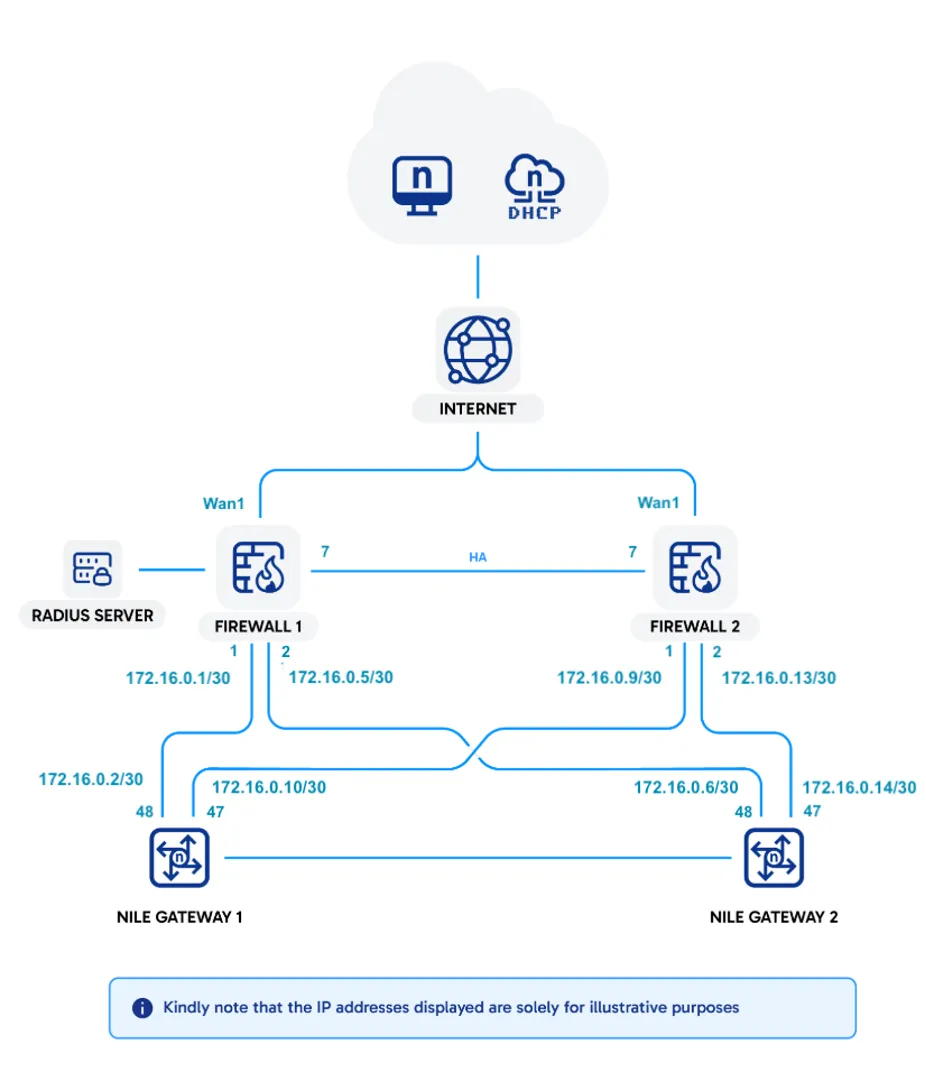
Configuration
There are several sections that need to be configured on the FortiGate as follows:
- Interfaces
- Wide Area Network (WAN) Interface(s)
- Nile Service Block (NSB) Interfaces
- Routing
- Static (WAN)
- OSPF (NSB)
- Firewall Policy
- High Availability (HA)
Interfaces
WAN
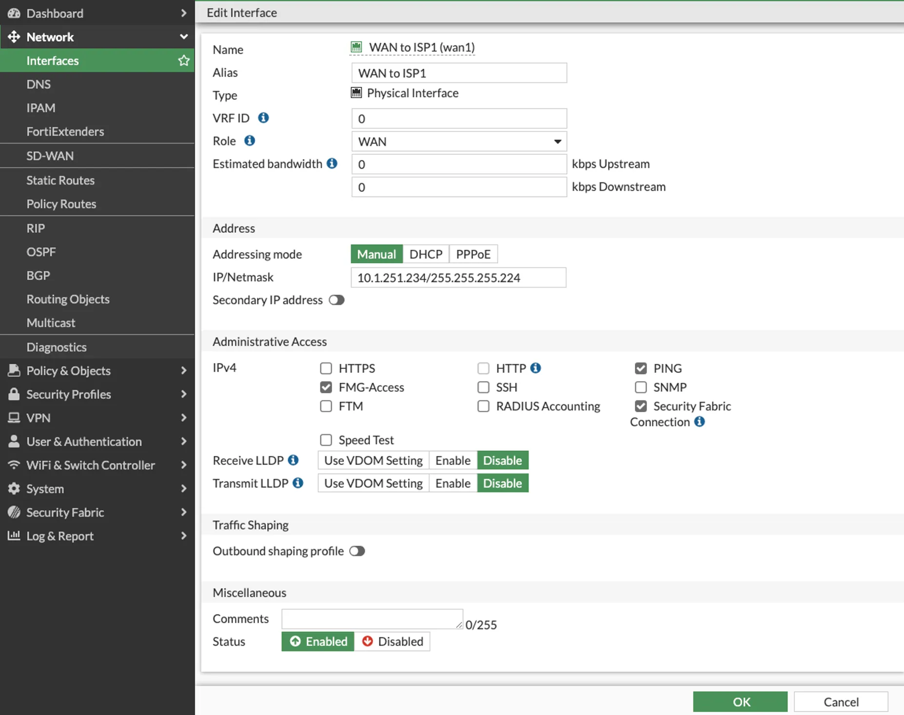
To set a WAN Interface, navigate to Network > Interfaces > [WAN Interface], and fill in the following information:
- Name: ISP1
- Alias: Details of the ISP
- VRF ID: Default (0)
- Role: WAN
- Addressing Mode: Manual
- IP/Netmask: IP address/netmask of WAN interface (example used 10.1.251.234/27)
- Administrative Access: Allow the required IPv4 services
- Status: Enabled
Click the “OK” button when done.
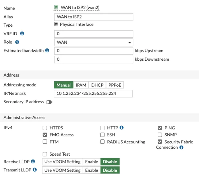
In case of a second ISP connected to WAN2 interface, configure that interface in a similar manner:
NSB Interfaces
Two (2) physical interfaces will be used to connect the two Nile Gateways.
However, each FortiGate interface will be configured with a primary and a secondary IP address. The secondary IP will be automatically used on the Passive firewall by OSPF in case of a failover.
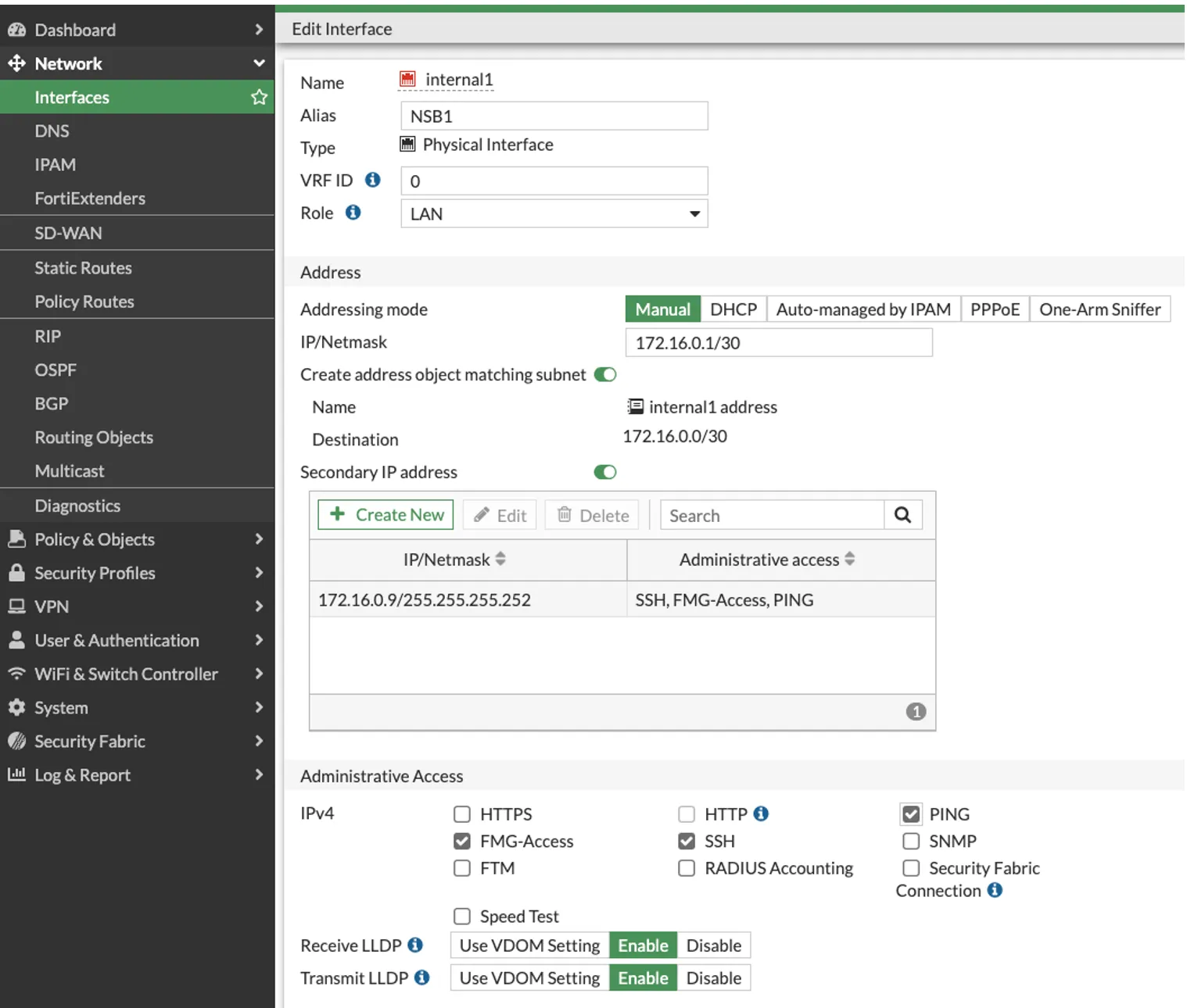
Navigate to Network > Interfaces and select the first physical Interface to be used (internal1 in this example)
- Alias: NSB1
- VRF ID: 0
- Role: LAN
- Addressing Mode: Manual
- IP/Netmask: IP address/netmask of interface (example used 172.16.0.1/30)
- Secondary IP address: IP address to be used on Passive FW ( example used 172.16.0.9/30)
- Administrative Access: Allow the required IPv4 services to include PING
- Receive/Transmit LLDP: Enable
- Status: Enabled
Click the “OK” button when done.
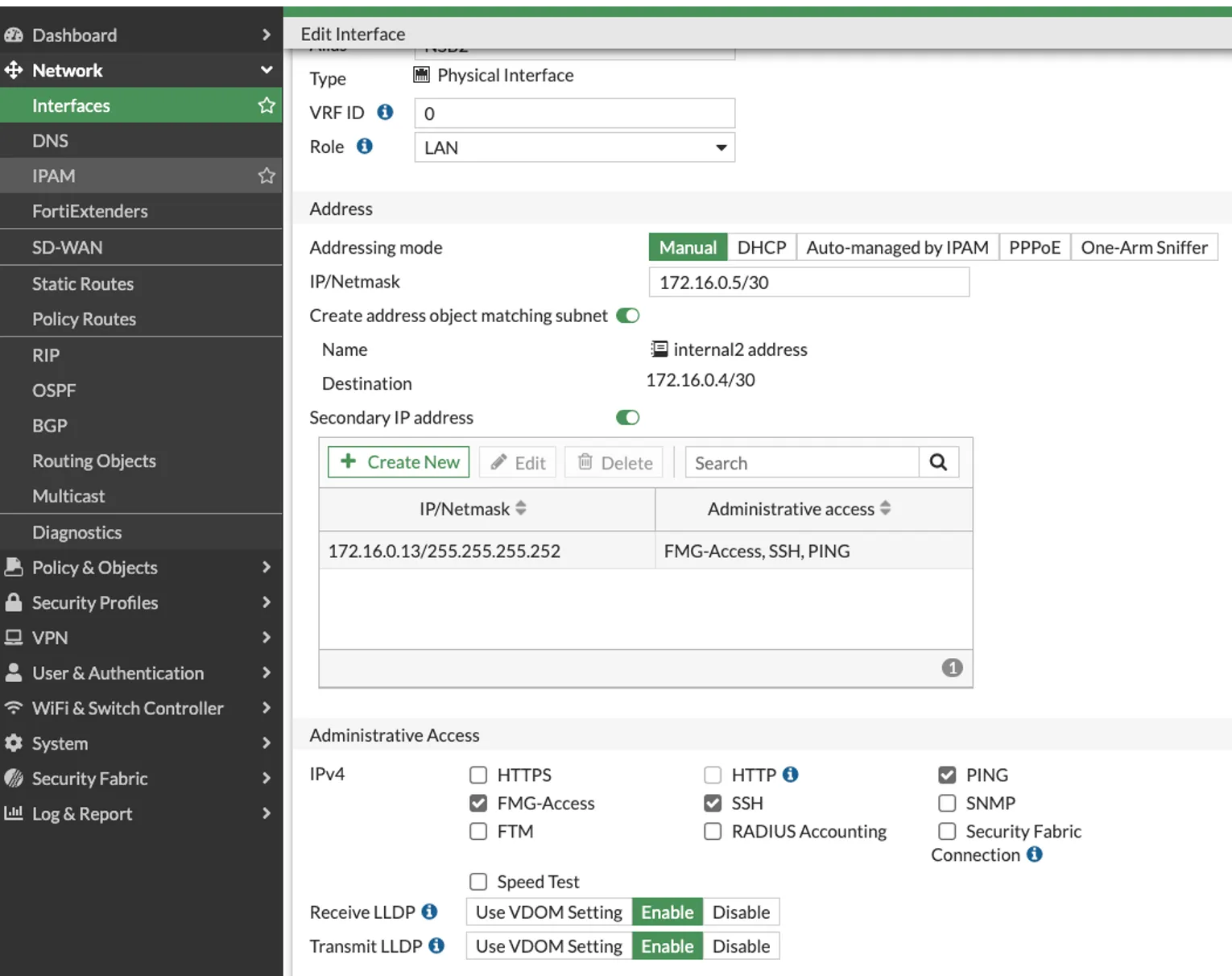
Similarly, navigate to Network > Interfaces and select the second physical Interface to be used (internal2 in this example)
- Alias: NSB2
- VRF ID: 0
- Role: LAN
- Addressing Mode: Manual
- IP/Netmask: IP address/netmask of interface (example used 172.16.0.5/30)
- Secondary IP address: IP address to be used on Passive FW (example used 172.16.0.13/30)
- Administrative Access: Allow the required IPv4 services to include PING
- Receive/Transmit LLDP: Enable
- Status: Enabled
- Click the “OK” button when done.
Nile Zone
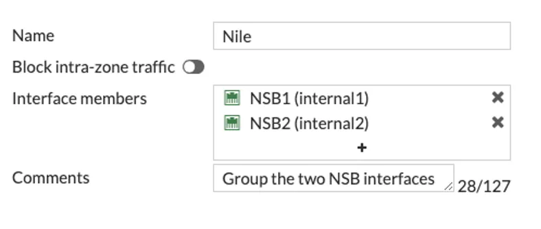
To simplify policy rules, it may be useful to group both NSB interfaces into a single zone entity (Nile in this document)
While in the Network > Interfaces page, click Create New > zone to create the Nile zone, and add NSB1 and NSB2 as interface members.
If traffic flow within the zone is desired (East-West traffic), leave the radio button Block intra-zone traffic unchecked.
Routing
Static (WAN)
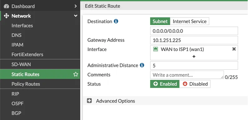
Navigate to Network > Static Routes > Create New, and enter the
- Destination > subnet: 0.0.0.0/0
- Gateway Address: supplied by the ISP (example used: 10.1.251.225)
- Interface: Select the WAN interface connected to ISP (Wan1 in this example)
- Administrative Distance: 5 (the lower the AD, the higher the priority)
- Status: Enabled
Click the “OK” button when done.
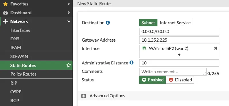
In case of a second ISP, this document covers the traditional WAN failover, whereby a default route to ISP2 is configured with a higher Administrative Distance (10) to make ISP1 primary and ISP2 secondary:
OSPF (NSB)
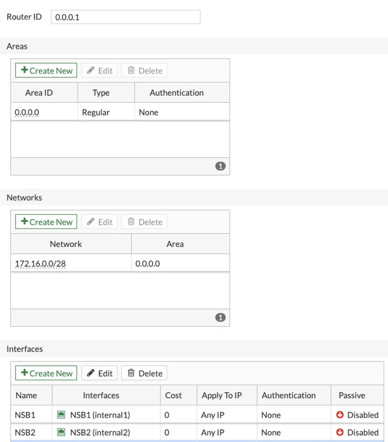
Navigate to Network > OSPF:
- Router ID: Use 0.0.0.1 and not any of the LAN interfaces IP address
- Areas: Create New (Area ID: 0.0.0.0 || Type: Regular || Authentication: None)
- Networks: Create New (Area: 0.0.0.0 || IP/Netmask: 0.0.0.0 0.0.0.0)
- Interfaces:
- Create New (Name: NSB1 || Interface: NSB1(internal1) || Cost: 0 || Authentication: None || Network type: Point to point || Hello interval: 1 || Dead interval: 4
- Similarly, create New (Name: NSB2 || Interface: NSB2(internal2) || Cost: 0 || Authentication: None || Network type: Point to point ||Hello interval: 1 || Dead interval: 4
- Inject default route: Always
Then click the Apply button to save the changes.
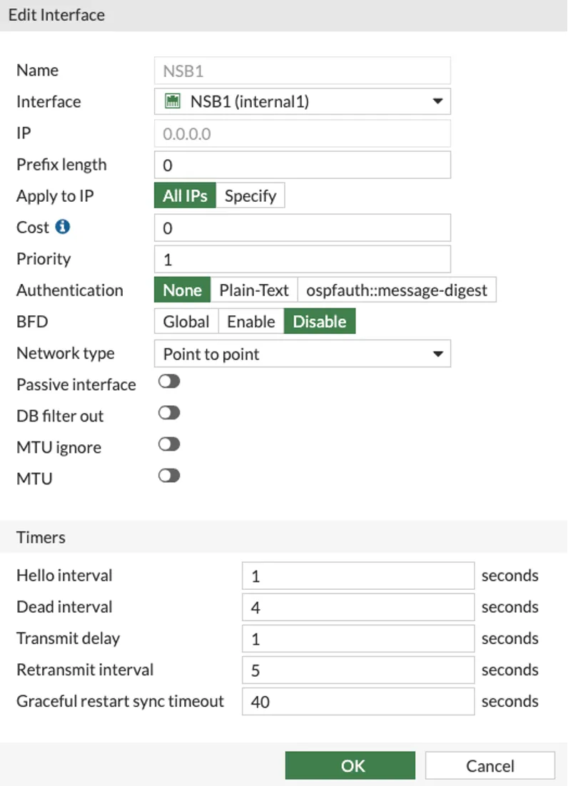
The OSPF configuration used in this document is illustrated below:
Firewall Policy
This section outlines the firewall policy requirements necessary to allow the Nile Service Block (NSB) to communicate with the Nile Cloud and to enable both wired and wireless clients to access the Internet. Firewall hardening and advanced security best practices are outside the scope of this document.
By default, the FortiGate firewall applies an implicit deny rule to all traffic. Therefore, explicit security policies must be configured to permit the required traffic flows listed below:
- NSB subnets – Including uplink /30 networks, NSB infrastructure subnets, and Sensor subnets, must be allowed outbound access to the Internet for HTTPS, DNS and NTP services.
- Nile wired and wireless client subnets – Must be permitted outbound Internet access.
- NSB to Server Farm – The NSB must be allowed to communicate with the server farm for infrastructure services such as DHCP and RADIUS, as required.
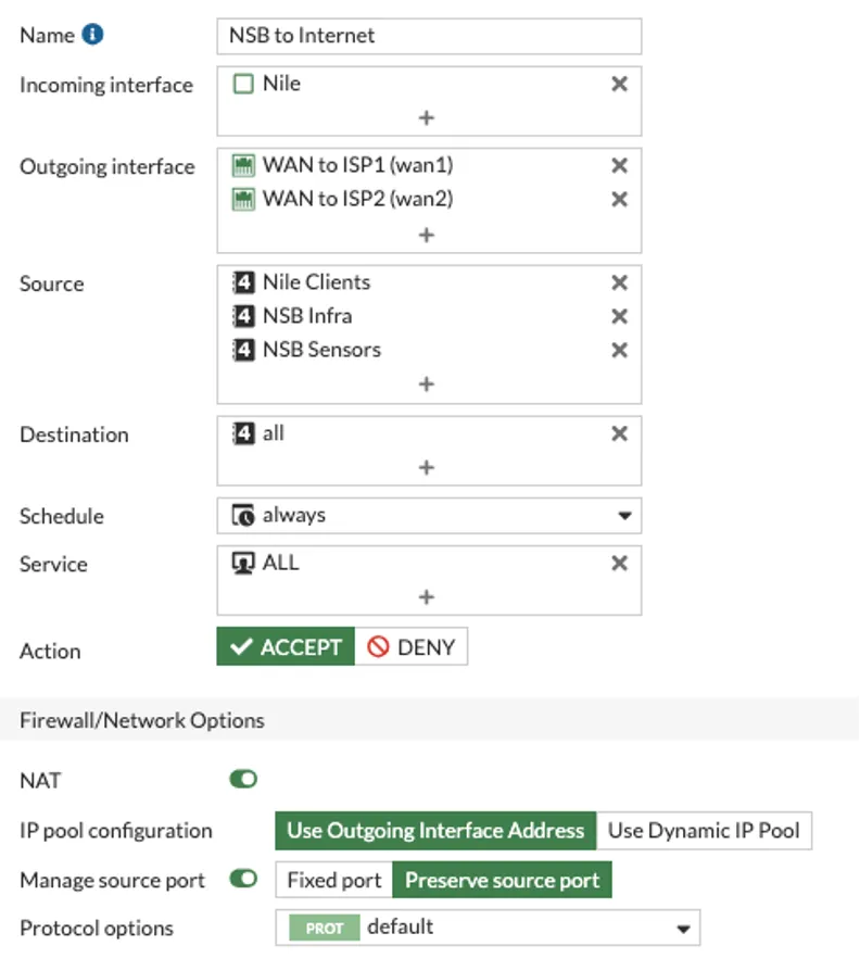
For illustration purposes, the following policy example allows any traffic from the Nile zone to the Internet
Navigate to Policy & objects > Firewall Policy > Create new:
- Name: Provide a name to the rule
- Incoming Interface: Select the ‘Nile’ zone
- Outgoing Interface: Wan1 and Wan2
- Source : NSB Infra, NSB Sensors, NSB clients
- Destination : ALL
- Schedule : Always
- Service : ALL
- Action : ACCEPT
- NAT : on
- IP pool Configuration: Use Outgoing Interface Address
- Manage source port : Preserve source port
High Availability (HA)
This section covers the FortiGate Active-Passive High Availability (HA).
FortiGate NGFW has the following requirements for two units to be configured for High Availability (HA):
- Hardware Match: Both units must be the same model with identical firmware versions.
- Heartbeat Interfaces: Dedicated ports must be directly connected or isolated via dedicated VLAN to synchronize session and configuration data.
This document uses a single heartbeat port on each FortiGate unit with a direct connection between the two units.
Primary FortiGate
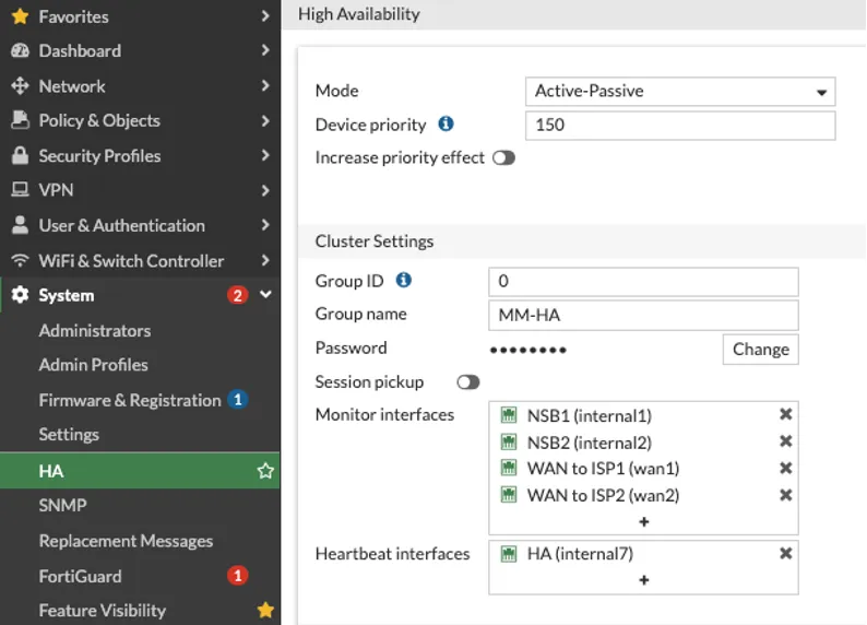
Navigate to System > HA and configure the following:
- Mode: Set to Active-Passive
- Device priority: Set it to a higher value (e.g. 200) than the Secondary (default is 128) to dictate which becomes the Primary.
- Cluster Settings: Define a Group ID, Group name and Password. These must be identical on both units.
- Heartbeat interfaces: Select the dedicated interface.
- Monitor interfaces: Could be defined once the HA is operational.
Click the “OK” button when done.
Secondary FortiGate
- Factory reset the secondary unit that will be in the cluster.
- Configure GUI access and set the host name in System > Settings to be different than the Primary unit.
- Repeat steps 1, 3 and 4 outlined in the Primary HA setup, omitting step 2 (device priority).
- Connect the two FortiGate units via their dedicated HA heartbeat ports.
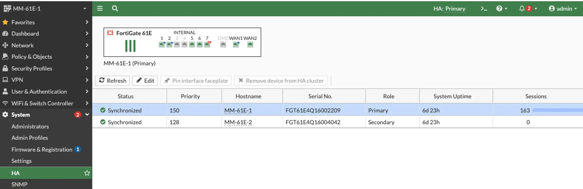
The HA status can be viewed on the Primary Unit HA page: