IPSec Hub Connectivity
1. Overview
Some networks would require a private, encrypted path back to customer-controlled infrastructure — legacy applications, regulated data, or partner extranets. For these, the Nile Edge engine terminates IPSec tunnels from the Nile site to one or more customer-controlled hubs (for example, a Datacenter or a cloud VPC). Tunnel survivability is owned by the same Adaptive Path Selection (APS) loop that Nile already runs across public-internet paths.
Nile implements this capability as a hub-and-spoke model:
- Spokes — every Nile site participating in the feature.
- Hubs — the customer-controlled primary and standby IPSec termination points.
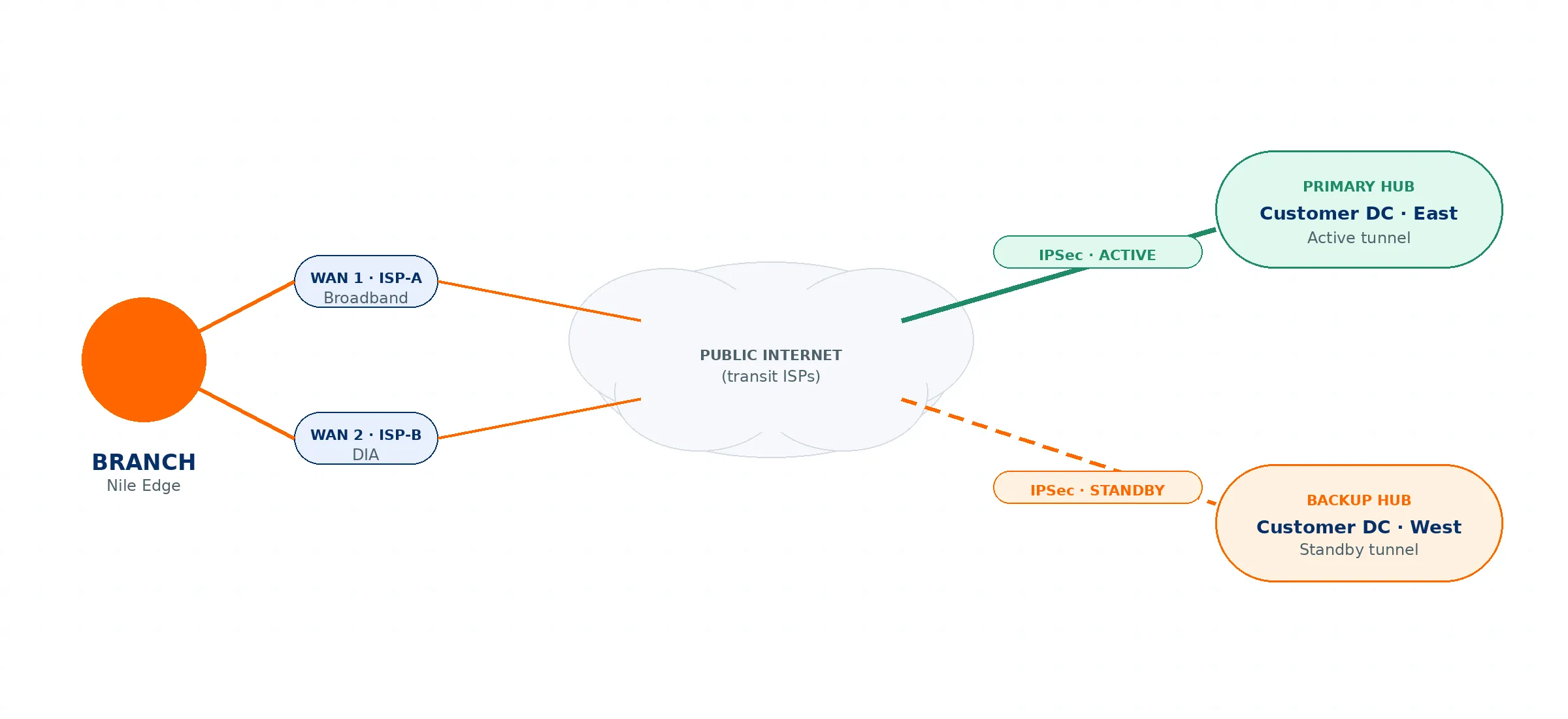
Figure 1: High-level IPSec hub topology. Both tunnels are kept up; Adaptive Path Selection owns the fail-over decision.
Key behaviors at a glance:
- The first ISP link configured during site bringup is used to form the IPSec tunnels to both the primary and standby hubs.
- The active Nile Edge engine establishes tunnels to both hubs and keeps them up; routing sends remote-subnet traffic to the primary hub by default.
- If the primary hub fails, Dead Peer Detection (DPD) triggers a route switch to the standby tunnel.
- If the active Edge engine fails, the second Edge engine takes over and repeats the process.
2. Prerequisites
Complete the following before configuring IPSec tunnels:
- Nile Edge Service subscription. IPSec hub connectivity is delivered as part of the Nile Edge Service; the site must be subscribed.
- Supported Nile Service Block version. Nile Support confirms that the Nile Service Block at the site is running the software version required to support this feature.
- Site configuration completed first. Finish the site's settings — DHCP, authentication, segments, and wireless — before configuring IPSec.
Why order matters: The IPSec configuration depends on the completed site settings. The Source Segments offered during tunnel creation are derived from the segments defined for the sites in the selected scope. If the site settings are not complete, the expected segments will not appear in the tunnel configuration.
3. Architecture & Failover Behavior
3.1 Tunnel establishment
During site bringup, the first ISP (WAN) link is designated for IPSec, and its public IP is used as the local tunnel endpoint. The active Nile Edge engine forms IPSec tunnels from this link to both the primary and standby hubs. Both tunnels are brought up and kept up at all times (IKE SA and CHILD SA established to each hub).
3.2 Steady-state routing
Although both tunnels are established, the system programs routes so that the gateway for the remote (hub-side) subnets points to the primary hub. The primary tunnel carries traffic by default; the standby tunnel stays up but idle.
3.3 Primary hub failure
The Nile Edge engine continuously monitors peer liveness via Dead Peer Detection (DPD). If the primary peer is declared dead and the standby tunnel is established, the engine repoints the gateway for the remote subnets to the standby tunnel, and traffic continues over the backup hub. Adaptive Path Selection owns the fail-over decision.
3.4 Edge engine failure
If the active Nile Edge engine itself fails, the second available Edge engine takes over and repeats the same sequence: it forms IPSec tunnels to both the primary and standby hubs, activates routing to the primary hub, and switches to the standby tunnel based on dead peer detection.
4. Hub Model & Regional (Multi-Hub) Scoping
4.1 Hub model
Each branch designates one or two hubs:
- Primary hub — the active tunnel under normal operation.
- Backup hub — a geo-diverse second termination point; the standby tunnel.
When two hubs are configured, both tunnels are kept up at all times. The active hub carries traffic by default; the backup hub carries traffic only when the active hub is unreachable.
Hub model parameters are configured per branch in the portal. For each hub the customer provides:
- Hub IP / FQDN (primary and backup)
- Pre-shared key or certificate reference (per hub)
- Encryption domain — the prefixes that should be tunnelled (the remote subnets)
4.2 Regional / multi-hub scoping
When creating tunnels you choose the sites under scope. This lets a customer with multiple regional hubs map sites to the nearest hub — for example, scope all West Coast sites to the West Coast regional hub, and all East Coast sites to the East Coast regional hub. You can therefore define multiple primary/standby hub pairs and attach them to different sets of sites defined on the Nile Portal.
5. Portal Configuration
Step 1 — General configuration & site scope
- Enter a Name for the tunnel.
- Set Priority — choose Primary or Secondary from the dropdown.
- Choose the sites that participate in the tunnel: select All Sites, or Select Scope and pick the specific sites.
- Once a site is selected, the portal displays the public IP address(es) of the first link added during that site's bringup. Use these as the tunnel endpoints to configure on the hub side.
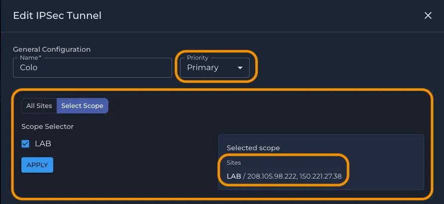
Figure 2: General configuration — tunnel name, Priority (Primary/Secondary), and site scope selection. The Selected scope panel surfaces the site's first-link public IPs to use as hub-side endpoints. (Public IPs masked.)
Step 2 — Peer configuration & policy
- Peers — enter the hub's Public IP / Hostname / Remote ID and the Shared Secret. These peer values are unique per tunnel — a different peer IP and shared secret for the primary and standby tunnels.
- Source Segments — the segments belonging to the selected sites. These are populated from the site configuration (hence the site-settings prerequisite).
- Remote Subnets — the subnets that reside on the hub end (inside the data center or cloud). Enter in IPv4 CIDR notation (e.g., 10.0.0.0/8); separate multiple values with commas.
- IPSec Policy — choose a preset (see Section 6).
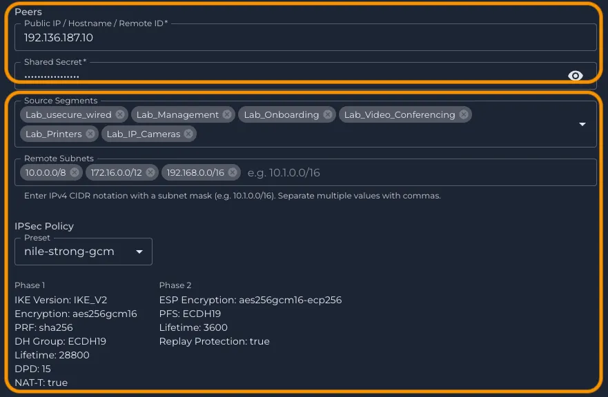
Figure 3: Primary peer configuration — Peer Public IP & Shared Secret (unique per tunnel), Source Segments (from the selected sites), Remote Subnets (hub-side subnets), and the IPSec Policy preset. (Public IP masked; shared secret hidden.)
Repeat for the standby tunnel: Create a second tunnel with Priority = Secondary using the backup hub's peer details (its own Public IP/Hostname and Shared Secret).
6. Cryptographic Suite (Policy Presets)
Rather than exposing a dropdown for every individual Phase 1 / Phase 2 parameter, Nile provides a set of curated IPSec policy presets. These cover almost all use cases and make it easy to configure tunnels consistently across the fleet:
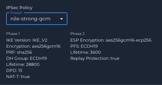
- nile-strong-gcm — strongest GCM-based suite (AES-256-GCM, ECDH19).
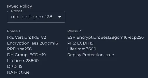
- nile-perf-gcm-128 — performance-optimized GCM suite (AES-128-GCM, ECDH19).
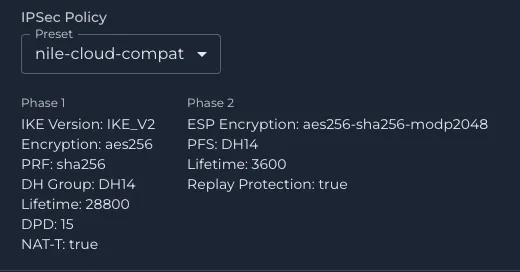
- nile-cloud-compat — broad cloud compatibility (AES-256 / SHA-256, DH14 / MODP2048).
If you require specific Phase 1 / Phase 2 settings beyond these presets, please reach out to Nile Support.
Phase | Parameter | nile-strong-gcm | nile-perf-gcm-128 | nile-cloud-compat |
|---|---|---|---|---|
Phase 1 | IKE Version | IKE_V2 | IKE_V2 | IKE_V2 |
Phase 1 | Encryption | aes256gcm16 | aes128gcm16 | aes256 |
Phase 1 | PRF | sha256 | sha256 | sha256 |
Phase 1 | DH Group | ECDH19 | ECDH19 | DH14 |
Phase 1 | Lifetime (s) | 28800 | 28800 | 28800 |
Phase 1 | DPD (s) | 15 | 15 | 15 |
Phase 1 | NAT-T | true | true | true |
Phase 2 | ESP Encryption | aes256gcm16-ecp256 | aes128gcm16-ecp256 | aes256-sha256-modp2048 |
Phase 2 | PFS | ECDH19 | ECDH19 | DH14 |
Phase 2 | Lifetime (s) | 3600 | 3600 | 3600 |
Phase 2 | Replay Protection | true | true | true |